
| Line 32: | Line 32: | ||
</math> |
</math> |
||
| − | where <math>h</math> is the heat transfer coefficient between the membrane and the ambient air in <math>W/(m^{-2} K^{-1})</math>. |
+ | where <math>h</math> is the heat transfer coefficient between the membrane and the ambient air in <math>W/(m^{-2} K^{-1})</math>. |
| − | |||
| − | |||
==Discretization== |
==Discretization== |
||
Revision as of 16:04, 16 November 2012
Description of the model
A silicon nitride membrane (SiN membrane) can be a part of a gas sensor, but also a part of an infra-red sensor, a michrothruster, an optimical filter etc. This structure resembles a microhotplate similar to other micro-fabricated devices such as gas sensors [1] and infrared sources [2]. See Fig.1.
The governing heat transfer equation in the membrane is:
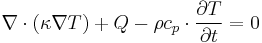
where  is the thermal conductivity in
  , cp is the specific heat capacity in
  ,
,  is the mass density in
  and
and  is the temperature distribution. We assume a homogeneous heat generation rate over a lumped resistor:

with  the heat generation rate per unit volume in
  .
We use the initial condition
.
We use the initial condition  , and the
Dirichlet boundary condition
, and the
Dirichlet boundary condition  at the bottom of
the computational domain.
at the bottom of
the computational domain.
The convection boundary condition at the top of the membrane is
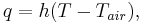
where  is the heat transfer coefficient between the membrane and the ambient air in
 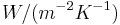 .
.
Discretization
Under convection boundary condition and assuming  , spatial discretization of the heat transfer model leads to the parametrized system as below,

where the volumetric heat capacity  , thermal conductivity
and the heat transfer coefficient between the membrane
and the ambient air
, thermal conductivity
and the heat transfer coefficient between the membrane
and the ambient air  , are kept as parameters.
Here  is either a constant heat resistivity
  , or
, or 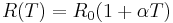 , which depends linearly on the temperature. Here we use
  and temperature coefficient
  . The model was created and meshed in ANSYS. It contains a constant load vector
  corresponding to the constant input power of
  . The number of degrees of freedom is
  .
.
The input function  is a step function with the value
  , which disappears at the time
  . This means between
  and input is one and after that it is zero. However, be aware that is just a factor with which the load vector B is multiplied and which corresponds to the heating power of . This means if one keeps as suggested above, the device is heated with for the time length of 0.02s and after that the heating is turned off. If for whatever reason, one wants the heating power to be
  , then has to be set equal to two, etc...
When , it is a function of the state vector and hence, the system has non-linear input. (It is also called a weakly nonlinear system.)
, then has to be set equal to two, etc...
When , it is a function of the state vector and hence, the system has non-linear input. (It is also called a weakly nonlinear system.)
Data information
The system matrices are in MatrixMarket format (http://math.nist.gov/MatrixMarket/) and can be downloaded here File:Matrices gassensor.tgz. The files named by *. correspond to the system matrices , respectively. The files named by
  correspond to
  . The file named by
  corresponds to the load vector and the file named by
  corresponds to the output matrix
  .
.
References
[1] T. Bechtold, D. Hohfel, E. B. Rudnyi and M. Guenther, "Efficient extraction of thin-film thermal parameters from numerical models via parametric model order reduction," J. Micromech. Microeng. 20(2010) 045030 (13pp).
Contact information: