 Note: This page has not been verified by our editors.
| Background | |
|---|---|
| Benchmark ID |
|
| Category |
CRC-TR-96 |
| System-Class |
LTI-FOS |
| Parameters | |
| nstates |
1265497
|
| ninputs |
|
| noutputs |
|
| nparameters |
0 |
| components |
A, B, C, E |
| Copyright | |
| License |
Creative Commons Attribution 4.0 International |
| Creator |
|
| Editor | |
| Location | |
__NUMBEREDHEADINGS__
Motivation
Due to the increasing interest in manufacturing accuracy without an additional energy demand for cooling, knowledge about the thermo-elastic behavior of entire machine tools becomes crucial. Methods to correct the thermally induced position error between the tool-center-point (TCP) and the workpiece in real-time are needed. Therefore, reduced-order models that enable a fast simulation of entire machine tools are applied in the design and production process.
Description

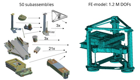
The MAX benchmark is a linear time-invariant thermal model of the demonstrator machine tool MAX(Fig. 1). Due to its lightweight construction based on aluminium structures, low heat capacities and high thermal coefficients of expansion are to be expected [1]. It is divided into 50 stationary subassemblies (SA), see Fig. 2. The thermal finite element (FE) model was generated in ANSYS and afterwards the model was exported for post-processing as described in [2]. The interaction between the subassemblies is modeled by contact boundary conditions. The evolution of the temperature field is modeled with the heat equation
with
and
- number of the subassembly, - temperature - specific heat capacity - density - heat conductivity - domain of the k-th subassembly - contact boundary of the k-th subassembly (partly time varying, moves with the position of the z-slide (considered as heat flow)) - heat transfer coefficient between a subassembly and the ambient air - external temperature - contact boundary with the ambience - heat transfer coefficient between two subassemblies - temperature of the contact area of subassembly k.
The finite element discretization of the heat conduction models leads to the system
with
- capacity matrix - conductivity matrix - state vector (discrete temperature) - input map - input vector - output vector - output map.
Data
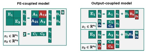
The system matrices are available in the .mat file format and can be downloaded from Zenodo. The model has degrees of freedom and is available for two different coupling approaches, which are explained in more detail in [2], see also Fig. 3:
- A so called output-coupled model: In this case, an input-output coupling was used, i.e., the model is block diagonal with a total number of inputs and outputs. Thus the subassemlby models can be reduced separately for structure preserving MOR. The block diagonal system can be split into a set of matrices for each subassembly by the script "generate_subsystems.m".
- A so called FE-coupled model: In this case, the subassemblies are coupled on FE-level, i.e., the conductivity matrix A of the overall system has additional (off-diagonal) coupling blocks. Thus the subassembly models cannot be reduced separately anymore. There is one set of matrices for the overall model with inputs and outputs.
Origin
The MAX is used as an experimental machine tool in the CRC/TR 96 Project-ID 174223256 financed by the German Research Foundation DFG.
References
- ↑ K. Großmann, ed., "Thermo-energetic Design of Machine Tools", Springer International Publishing, Switzerland, pp. 9-10, 2015.
- ↑ 2.0 2.1 J. Vettermann, S. Sauerzapf, A. Naumann, J. Saak, P. Benner, M. Beitel- schmidt and R. Herzog, "Model order reduction methods for coupled machine tool models", MM Science Journal, Special Issue ICTIMT 2021, 2021.