(Created page with 'test 1,2') |
|||
| Line 1: | Line 1: | ||
| + | [[Category:benchmark]] |
||
| − | test 1,2 |
||
| + | [[Category:parametric system]] |
||
| + | [[Category:linear system]] |
||
| + | [[Category:time invariant]] |
||
| + | [[Category:geometrical parameters]] |
||
| + | [[Category:two parameters]] |
||
| + | [[Category:second order system]] |
||
| + | |||
| + | ==Model Description== |
||
| + | |||
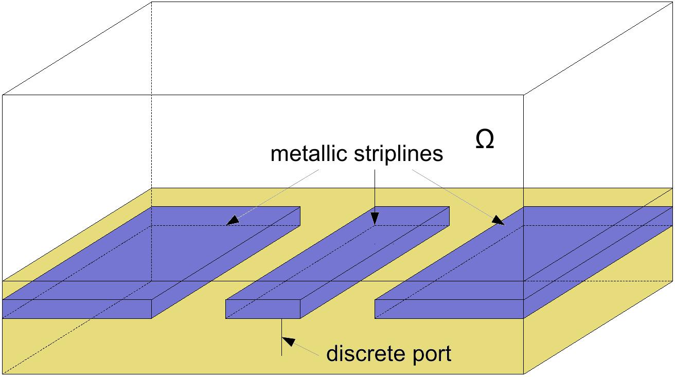
| + | A coplanar waveguide is a microwave semiconductor device, which is governed by maxwell's equations. |
||
| + | The coplanar waveguide considered with dielectric overlay, i.e. a transmission line shielded within two layers of multilayer board with 0.5mm thickness are buried in a substrate with 10mm thickness and relative permittivity |
||
| + | <math> \epsilon_r = 4.4 </math> and relative permeability <math> \mu_r = 1 </math>, and low conductivity <math> \sigma = 0.02 S/m </math>. The low-loss upper layer has low permittivity <math> \epsilon_r = 1.07 </math> and |
||
| + | <math> \sigma = 0.01 S/m </math>. The whole structure is enlosed in a metallic box of dimension 140mm by 100mm by 50mm. The discrete port with 50ohm lumped load imposes 1 A current as the input to the one side of the strip. The voltage along the discrete port 2 at the end of the other side of coupled lines is integrated as the output. |
||
| + | |||
| + | [[File:CoplanarWaveguide.jpg]] |
||
| + | |||
| + | |||
| + | ==Matrices and Data== |
||
| + | |||
| + | ==References== |
||
Revision as of 14:37, 12 November 2012
Model Description
A coplanar waveguide is a microwave semiconductor device, which is governed by maxwell's equations.
The coplanar waveguide considered with dielectric overlay, i.e. a transmission line shielded within two layers of multilayer board with 0.5mm thickness are buried in a substrate with 10mm thickness and relative permittivity
 and relative permeability
  , and low conductivity
  . The low-loss upper layer has low permittivity
  and
and
 . The whole structure is enlosed in a metallic box of dimension 140mm by 100mm by 50mm. The discrete port with 50ohm lumped load imposes 1 A current as the input to the one side of the strip. The voltage along the discrete port 2 at the end of the other side of coupled lines is integrated as the output.

