
Vettermann (talk | contribs) m (add link to data) |
Vettermann (talk | contribs) (add citation) |
||
| (One intermediate revision by the same user not shown) | |||
| Line 9: | Line 9: | ||
[[Category:MIMO]] |
[[Category:MIMO]] |
||
[[Category:CRC-TR-96]] |
[[Category:CRC-TR-96]] |
||
| + | |||
| + | {{Infobox |
||
| + | |Title = MAX stand |
||
| + | |Benchmark ID = |
||
| + | * maxStandSA1_n25872m10q10 |
||
| + | * maxStandSA2_n39527m30q30 |
||
| + | * maxStandSA3_n13551m6q6 |
||
| + | * maxStandSA4_n4813m23q23 |
||
| + | |Category = CRC-TR-96 |
||
| + | |System-Class = AP-LTI-FOS |
||
| + | |nstates = |
||
| + | * 25872 |
||
| + | * 39527 |
||
| + | * 13551 |
||
| + | * 4813 |
||
| + | |ninputs = |
||
| + | * 10 |
||
| + | * 30 |
||
| + | * 6 |
||
| + | * 23 |
||
| + | |noutputs = |
||
| + | * 10 |
||
| + | * 30 |
||
| + | * 6 |
||
| + | * 23 |
||
| + | |nparameters = |
||
| + | * 2 |
||
| + | * 1 |
||
| + | * 1 |
||
| + | * 1 |
||
| + | |components = A, B, C, E |
||
| + | |License = Creative Commons Attribution 4.0 International |
||
| + | |Creator = |
||
| + | * CRC/TR 96: |
||
| + | * Chair of Machine Tools Development and Adaptive Controls (Technische Universität Dresden), |
||
| + | * Mathematics in Industry and Technology (Technische Universität Chemnitz) |
||
| + | |Editor = [[User:Vettermann]] |
||
| + | |Zenodo-link = https://zenodo.org/records/10039696 |
||
| + | }} |
||
__NUMBEREDHEADINGS__ |
__NUMBEREDHEADINGS__ |
||
| Line 75: | Line 114: | ||
:<math> |
:<math> |
||
\begin{align} |
\begin{align} |
||
| − | E_k\dot{T}_k&=( |
+ | E_k\dot{T}_k&=(A_k-\sum_{i=1}^{l_k}\kappa_{ext_i}(t)A^i_k)T_k+B_k u_k(t),\quad k=1,\dots,4\\ |
y_k(t)&=C_k T_k,\\ |
y_k(t)&=C_k T_k,\\ |
||
\end{align} |
\end{align} |
||
| Line 85: | Line 124: | ||
| <math> E_k \in \mathbb{R}^{n\times n} </math> || - FE mass matrix |
| <math> E_k \in \mathbb{R}^{n\times n} </math> || - FE mass matrix |
||
|- |
|- |
||
| − | | <math> |
+ | | <math> A_k \in \mathbb{R}^{n\times n} </math> || - basic stiffness matrix (discrete Laplacian) |
|- |
|- |
||
| <math> l_k \in \mathbb{R} </math> || - number of boundary conditions with the ambience (Robin boundary conditions (RBC)) |
| <math> l_k \in \mathbb{R} </math> || - number of boundary conditions with the ambience (Robin boundary conditions (RBC)) |
||
|- |
|- |
||
| − | | <math> |
+ | | <math> A^i_k \in \mathbb{R}^{n\times n} </math> || - boundary mass matrix (part of stiffness matrix arising from RBC) |
|- |
|- |
||
| <math> T_k \in \mathbb{R}^n </math> || - state vector (discrete temperature) |
| <math> T_k \in \mathbb{R}^n </math> || - state vector (discrete temperature) |
||
| Line 109: | Line 148: | ||
==Data== |
==Data== |
||
| − | The system matrices |
+ | The system matrices (heat transfer coefficients with the ambience may be varied) and files for a simulation of the model in time domain can be downloaded from [https://zenodo.org/records/10039696 Zenodo]. There is a set of matrices for each subassembly. The numbering of the subassemblies is shown in Fig. 1. Further the archive contains a MATLAB file with the description and computation of the contacts between the subassemblies and a file for the simulation of a work process. The overall system dimension is <math> n=83\,763 </math> with |
{| class="wikitable" style="margin: auto;" |
{| class="wikitable" style="margin: auto;" |
||
| Line 149: | Line 188: | ||
The '''MAX stand''' is used as a demonstrator in the [https://morwiki.mpi-magdeburg.mpg.de/morwiki/index.php/Category:CRC-TR-96 CRC/TR 96] Project-ID 174223256 financed by the German Research Foundation DFG. |
The '''MAX stand''' is used as a demonstrator in the [https://morwiki.mpi-magdeburg.mpg.de/morwiki/index.php/Category:CRC-TR-96 CRC/TR 96] Project-ID 174223256 financed by the German Research Foundation DFG. |
||
| + | |||
| + | ==Citation== |
||
| + | |||
| + | To cite this benchmark, use the following references: |
||
| + | |||
| + | * For the benchmark itself and its data: |
||
| + | |||
| + | @misc{dataCRCTR9623, |
||
| + | author = {Collaborative Research Centre Transregio 96 (CRC/TR 96)}, |
||
| + | title = {Model of a machine tool stand}, |
||
| + | howpublished = {hosted at {MORwiki} -- Model Order Reduction Wiki}, |
||
| + | year = 2023, |
||
| + | doi = {10.5281/zenodo.10039696} |
||
| + | } |
||
==References== |
==References== |
||
Latest revision as of 13:37, 26 October 2023
 Note: This page has not been verified by our editors.
| Background | |
|---|---|
| Benchmark ID |
|
| Category |
CRC-TR-96 |
| System-Class |
AP-LTI-FOS |
| Parameters | |
| nstates |
|
| ninputs |
|
| noutputs |
|
| nparameters |
|
| components |
A, B, C, E |
| Copyright | |
| License |
Creative Commons Attribution 4.0 International |
| Creator |
|
| Editor | |
| Location | |
1 Motivation
Due to the increasing interest in manufacturing accuracy without an additional energy demand for cooling, knowledge about the thermo-elastic behavior of entire machine tools becomes crucial. Methods to correct the thermally induced position error between the tool-center-point (TCP) and the workpiece in real-time are needed. Therefore, reduced-order models that enable a fast simulation of entire machine tools are applied in the design and production process.
2 Description

The MAX stand benchmark is a linear thermal model of a stand of the demonstrator machine tool MAX. Due to its lightweight construction based on aluminium structures, low heat capacities and high thermal coefficients of expansion are to be expected [1]. It is divided into four stationary subassemblies (SA): base, z-stand with guide rail and bottom plate, motor with belt housing, bearing seat and outer bearing ring as well as ball screw (spindle with inner bearing ring), see Fig. 1. The thermal finite element (FE) model was generated in ANSYS and afterwards the FE system matrices were exported for post-processing, such as MOR, to MATLAB. The interaction between the subassemblies is modeled by contact boundary conditions. The evolution of the temperature field is modeled with the heat equation
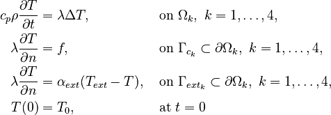
with

and

- number of the subassembly, 

- temperature 
- specific heat capacity 
- density 
- heat conductivity 
- domain of the k-th subassembly 
- contact boundary of the k-th subassembly (partly time varying, moves with the position of the z-slide (considered as heat flow)) 
- heat transfer coefficient between a subassembly and the ambient air 
- external temperature 
- contact boundary with the ambience 
- friction driven heat flow induced by the movement 
- heat transfer coefficient between two subassemblies 
- temperature of the contact area of subassembly k.
The finite element discretization of the heat conduction models leads to the four systems
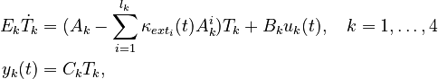
with

- FE mass matrix 
- basic stiffness matrix (discrete Laplacian) 
- number of boundary conditions with the ambience (Robin boundary conditions (RBC)) 
- boundary mass matrix (part of stiffness matrix arising from RBC) 
- state vector (discrete temperature) 
- input map 
- input vector 
- output vector 
- output map.
The movement of the z-slide is considered as position-dependent heat flows in the input  . The position of the z-slide in the MAX stand model is characterized by the position
 ![d \in [0, 0.7571]\text{ }m](/morwiki/images/math/a/1/9/a1936320be59ddf6e5277501bad6d194.png) of the z-slide on the spindle and the guide rail. To include this variability in the model the boundaries of the subassemblies
are divided into smaller parts and the average temperature of these parts is used for computing the input . To be more precise, the spindle and the guide rail are divided into 20 segments each. The segments are numbered from top to bottom, i.e. for the position
of the z-slide on the spindle and the guide rail. To include this variability in the model the boundaries of the subassemblies
are divided into smaller parts and the average temperature of these parts is used for computing the input . To be more precise, the spindle and the guide rail are divided into 20 segments each. The segments are numbered from top to bottom, i.e. for the position  the z-slide is in contact with segment 1 of the spindle and the guide rail.
In the simulation the calculated average temperature of an area in the current time step serves as input temperature of this area in the next time step and is also used for calculating the thermally dependent heat transfer coefficients. Thus the average temperatures of all contact areas are needed as outputs
the z-slide is in contact with segment 1 of the spindle and the guide rail.
In the simulation the calculated average temperature of an area in the current time step serves as input temperature of this area in the next time step and is also used for calculating the thermally dependent heat transfer coefficients. Thus the average temperatures of all contact areas are needed as outputs  . Further, the temperatures in certain nodes of interest complete the output . For more information concerning MOR for systems with moving loads see e.g. [2] and the references therein.
3 Data
The system matrices (heat transfer coefficients with the ambience may be varied) and files for a simulation of the model in time domain can be downloaded from Zenodo. There is a set of matrices for each subassembly. The numbering of the subassemblies is shown in Fig. 1. Further the archive contains a MATLAB file with the description and computation of the contacts between the subassemblies and a file for the simulation of a work process. The overall system dimension is  with
with
| Subassembly
|

|

|

|
| 1 | 
|

|
|
| 2 | 
|

|
|
| 3 | 
|

|
|
| 4 | 
|

|
|
4 Remarks
- This is a model with diagonal matrix
 .
. - The model was also used for numerical experiments presented in [3].
- For the simulation the system was shifted by the initial temperature
 to guarantee a zero inital value.
5 Origin
The MAX stand is used as a demonstrator in the CRC/TR 96 Project-ID 174223256 financed by the German Research Foundation DFG.
6 Citation
To cite this benchmark, use the following references:
- For the benchmark itself and its data:
 @misc{dataCRCTR9623,
   author = {Collaborative Research Centre Transregio 96 (CRC/TR 96)},
   title = {Model of a machine tool stand},
   howpublished = {hosted at {MORwiki} -- Model Order Reduction Wiki},
   year = 2023,
   doi = {10.5281/zenodo.10039696}
 }
7 References
- ↑ K. Großmann, ed., "Thermo-energetic Design of Machine Tools", Springer International Publishing, Switzerland, pp. 9-10, 2015.
- ↑ N. Lang, J. Saak and P. Benner, "Model Order Reduction for Systems with Moving Loads", at-Automatisierungstechnik, pp. 512–522, 2014.
- ↑ P. Benner, D. Palitta and J. Saak, "On an integrated Krylov-ADI solver for large-scale Lyapunov equations", Numer Algor 92, pp. 35–63, 2023.