
| Line 13: | Line 13: | ||
==Description== |
==Description== |
||
| − | [[File:Staender_Geom_white.jpg|thumb|right|120px|CAD Geometry]]The '''vertical stand''' represents a structural part of a machine tool. On one of its surfaces |
+ | [[File:Staender_Geom_white.jpg|thumb|right|120px|CAD Geometry]]The '''vertical stand''' represents a structural part of a machine tool. On one of its surfaces a pair of guide rails is located. Caused by a machining process a tool slide is moving on these rails. The machining process produces a certain amount of heat which is transported through the structure into the '''vertical stand'''. This heat source is considered to be a temperature input at the guide rails. This transfered heat amount leads to deformations within the device induced by the prevailed temperature field denoted by <math> x </math>. The evolution of this field is modeled by the heat equation |
:<math> |
:<math> |
||
| Line 25: | Line 25: | ||
</math> on <math> \Gamma_{slide} </math> (surface where the tool slide is moving on the guide rails), |
</math> on <math> \Gamma_{slide} </math> (surface where the tool slide is moving on the guide rails), |
||
| − | describing the heat transfer between the tool slide and the '''vertical stand''' |
+ | describing the heat transfer between the tool slide and the '''vertical stand'''. |
| + | The heat transfer to the ambience is given by the Robin-type boundary condition |
||
:<math> |
:<math> |
||
| Line 31: | Line 32: | ||
</math> on <math> \Gamma_{surf} </math> (remaining boundaries), |
</math> on <math> \Gamma_{surf} </math> (remaining boundaries), |
||
| − | which describes |
+ | which describes t. |
| + | |||
| + | |||
| ⚫ | |||
| + | |||
| ⚫ | |||
| + | |||
| ⚫ | |||
| + | |||
The heat load <math>q</math> induced by the slide and the external temperature <math>x_{ext}</math> serve as the input <math> u </math> of the corresponding state-space system. |
The heat load <math>q</math> induced by the slide and the external temperature <math>x_{ext}</math> serve as the input <math> u </math> of the corresponding state-space system. |
||
The motion of the tool slide and the associated variation of the affected input boundary are modeled by two different system representations. |
The motion of the tool slide and the associated variation of the affected input boundary are modeled by two different system representations. |
||
| + | |||
| + | ====Switched linear system==== |
||
| + | |||
| + | ====Linear Parameter-varying system==== |
||
==Acknowledgement & Origin== |
==Acknowledgement & Origin== |
||
| − | + | The base model was developed <ref name="LanSB15" />,<ref name="GalGM15" /> in the [http://transregio96.de Collaborative Research Centre Transregio 96] ''Thermo-Energetic Design of Machine Tools'' funded by the [http://www.dfg.de/en/index.jsp Deutsche Forschungsgemeinschaft] . |
|
==Data== |
==Data== |
||
| + | and investigated |
||
| + | ====Switched System Data==== |
||
| + | ====Parametric System Data==== |
||
The data file [[Media:Data_VertStand.tar.gz|Data_VertStand.tar.gz]] contains a MAT_File ''matrices.mat'' which consists of the matrices |
The data file [[Media:Data_VertStand.tar.gz|Data_VertStand.tar.gz]] contains a MAT_File ''matrices.mat'' which consists of the matrices |
||
| Line 65: | Line 81: | ||
and the fifth column of <math>B_{surf}</math> includes the missing upper <math>(y\in[1\,340,2\,010]mm)</math> part. |
and the fifth column of <math>B_{surf}</math> includes the missing upper <math>(y\in[1\,340,2\,010]mm)</math> part. |
||
| − | To clarify this partitioning the geometrical data is given as follows: |
||
| + | ==Citation== |
||
| ⚫ | |||
| + | To cite this benchmark, use the following references: |
||
| ⚫ | |||
| + | * For the benchmark itself and its data: |
||
| ⚫ | |||
| + | ::The MORwiki Community. '''Vertical Stand'''. MORwiki - Model Order Reduction Wiki, 2018. http://modelreduction.org/index.php/Vertical_Stand |
||
| + | |||
| + | @MISC{morwiki_vertstand, |
||
| + | author = {The {MORwiki} Community}, |
||
| + | title = {Vertical Stand}, |
||
| + | howpublished = {{MORwiki} -- Model Order Reduction Wiki}, |
||
| + | url = {<nowiki>http://modelreduction.org/index.php/Vertical_Stand</nowiki>}, |
||
| + | year = {2014} |
||
| + | } |
||
| + | |||
| + | * For the background on the benchmark: |
||
| + | |||
| + | @Article{morLanSB14, |
||
| + | author = {Lang, Norman and Saak, Jens and Benner, Peter}, |
||
| + | title = {Model Order Reduction for Systems with Moving Loads}, |
||
| + | journal = {at-Automatisierungstechnik}, |
||
| + | year = 2014, |
||
| + | volume = 62, |
||
| + | number = 7, |
||
| + | pages = {512--522}, |
||
| + | month = {June}, |
||
| + | publisher = {deGruyter}, |
||
| + | doi = {10.1515/auto-2014-1095} |
||
| + | } |
||
==References== |
==References== |
||
<references> |
<references> |
||
| + | |||
| + | |||
| + | <ref name="morLanSB14">N. Lang and J. Saak and P. Benner, |
||
| + | <span class="plainlinks">[https://doi.org/10.1515/auto-2014-1095 Model Order Reduction for Systems with Moving Loads] </span>, |
||
| + | in De Gruyter Oldenbourg: at-Automatisierungstechnik, Volume 62, Issue 7, Pages 512-522, 2014</ref> |
||
<ref name="LanSB15">N. Lang, J. Saak and P. Benner, <span class="plainlinks">[https://doi.org/10.1007/978-3-319-12625-8_8 Model Order Reduction for Thermo-Elastic Assembly Group Models] </span>, In: Thermo Energetic Design of Machine Tools, Lecture Notes in Production Engineering, 85-92, 2015</ref> |
<ref name="LanSB15">N. Lang, J. Saak and P. Benner, <span class="plainlinks">[https://doi.org/10.1007/978-3-319-12625-8_8 Model Order Reduction for Thermo-Elastic Assembly Group Models] </span>, In: Thermo Energetic Design of Machine Tools, Lecture Notes in Production Engineering, 85-92, 2015</ref> |
||
Revision as of 10:15, 13 March 2018
 Note: This page has not been verified by our editors.
1 Description

The vertical stand represents a structural part of a machine tool. On one of its surfaces a pair of guide rails is located. Caused by a machining process a tool slide is moving on these rails. The machining process produces a certain amount of heat which is transported through the structure into the vertical stand. This heat source is considered to be a temperature input at the guide rails. This transfered heat amount leads to deformations within the device induced by the prevailed temperature field denoted by  . The evolution of this field is modeled by the heat equation
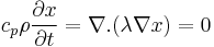
with the boundary conditions
 on
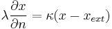
on  (surface where the tool slide is moving on the guide rails),
describing the heat transfer between the tool slide and the vertical stand. The heat transfer to the ambience is given by the Robin-type boundary condition
 on
on  (remaining boundaries),
which describes t.
Width ( direction):  ,
,
Height ( direction):
  ,
,
Depth ( direction):
The heat load  induced by the slide and the external temperature
  serve as the input
  of the corresponding state-space system.
The motion of the tool slide and the associated variation of the affected input boundary are modeled by two different system representations.
1.1 Switched linear system
1.2 Linear Parameter-varying system
2 Acknowledgement & Origin
The base model was developed [1],[2] in the Collaborative Research Centre Transregio 96 Thermo-Energetic Design of Machine Tools funded by the Deutsche Forschungsgemeinschaft .
3 Data
and investigated
3.1 Switched System Data
3.2 Parametric System Data
The data file Data_VertStand.tar.gz contains a MAT_File matrices.mat which consists of the matrices

in sparse format and a file with the coordinates of the mesh nodes called coord.txt.
Here  consists of all nodes located on the guide rails.
In order to get a parameter dependent matrix
 one has to pick the "active" nodes (nodes hit by tool carriage) at vertical position
  .
The "active" nodes are in the interval of
.
The "active" nodes are in the interval of ![[\mu-\frac{d}{2},\mu+\frac{d}{2}]](/morwiki/images/math/a/7/1/a71f92fd4be99066106491025fe32ad6.png) , where
, where  is the heigth of the slide.
The file coord.txt provided in Data_VertStand.tar.gz includes a column with indices followed by three additional columns containing the spatial coordinates  of the corresponding nodes.
The matrix  describes the locations where the external temperatures act on.
The first column is responsible for the input of the temperature at the clamped bottom slice of the structure.
Column 2 describes the ... part of the stand. Columns 3 to 5 describe different thresholds with respect to the height of ambient air temperature.
The third column includes the nodes of the lower third
describes the locations where the external temperatures act on.
The first column is responsible for the input of the temperature at the clamped bottom slice of the structure.
Column 2 describes the ... part of the stand. Columns 3 to 5 describe different thresholds with respect to the height of ambient air temperature.
The third column includes the nodes of the lower third  of the stand.
In column 4 all nodes of the middle third
of the stand.
In column 4 all nodes of the middle third 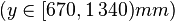 of the geometry are contained
and the fifth column of includes the missing upper
of the geometry are contained
and the fifth column of includes the missing upper ![(y\in[1\,340,2\,010]mm)](/morwiki/images/math/8/f/7/8f7ee61fb31ab9462369fff516b9d051.png) part.
part.
4 Citation
To cite this benchmark, use the following references:
- For the benchmark itself and its data:
- The MORwiki Community. Vertical Stand. MORwiki - Model Order Reduction Wiki, 2018. http://modelreduction.org/index.php/Vertical_Stand
   @MISC{morwiki_vertstand,
    author = {The {MORwiki} Community},
    title = {Vertical Stand},
    howpublished = {{MORwiki} -- Model Order Reduction Wiki},
    url = {http://modelreduction.org/index.php/Vertical_Stand},
    year = {2014}
   }
- For the background on the benchmark:
   @Article{morLanSB14,
     author =       {Lang, Norman and Saak, Jens and Benner, Peter},
     title =        {Model Order Reduction for Systems with Moving Loads},
     journal =      {at-Automatisierungstechnik},
     year =         2014,
     volume =       62,
     number =       7,
     pages =        {512--522},
     month =        {June},
     publisher =    {deGruyter},
     doi =          {10.1515/auto-2014-1095}
   }
5 References
- ↑ N. Lang, J. Saak and P. Benner, Model Order Reduction for Thermo-Elastic Assembly Group Models , In: Thermo Energetic Design of Machine Tools, Lecture Notes in Production Engineering, 85-92, 2015
- ↑ A. Galant, K. Großmann and A. Mühl, Thermo-Elastic Simulation of Entire Machine Tool , In: Thermo Energetic Design of Machine Tools, Lecture Notes in Production Engineering, 69-84, 2015
Cite error: <ref> tag with name "morLanSB14" defined in <references> is not used in prior text.