
| Line 14: | Line 14: | ||
Model Order Reduction for parameterized MEMS applications," PhD thesis, Department of Microsystems Engineering, |
Model Order Reduction for parameterized MEMS applications," PhD thesis, Department of Microsystems Engineering, |
||
University of Freiburg, Freiburg, Germany 2007.</ref>. Without applied external rotation, the paddles vibrate in phase |
University of Freiburg, Freiburg, Germany 2007.</ref>. Without applied external rotation, the paddles vibrate in phase |
||
| − | with the function <math>z(t),</math> see |
+ | with the function <math>z(t),</math> see <xr id="fig:gyro"/>. Under the influence of an external rotation about the <math>x</math>-axis (drawn |
in red), an additional force due to the Coriolis acceleration acts upon the |
in red), an additional force due to the Coriolis acceleration acts upon the |
||
paddles. This force leads to an additional small out-of-phase vibration |
paddles. This force leads to an additional small out-of-phase vibration |
||
Revision as of 08:49, 28 March 2013

Description
The device is a MEMS gyroscope based on the butterfly gyroscope [1] developed at the Imego institute in Gothenburg, Sweden (see also: http://simulation.uni-freiburg.de/downloads/benchmark/The Butterfly Gyro (35889), where a non-parametrized model for the device is given ). A gyroscope is a device used to measure angular rates in up to three axes.
The basic working principle of the gyroscope can be described as follows, see also [2]. Without applied external rotation, the paddles vibrate in phase
with the function  see xx--CrossReference--dft--fig:gyro--xx. Under the influence of an external rotation about the
  -axis (drawn
in red), an additional force due to the Coriolis acceleration acts upon the
paddles. This force leads to an additional small out-of-phase vibration
between two paddles on the same side of the bearing. This
out-of phase vibration is measured as the difference of the z-displacement
of the nodes with the red dots. Thus, measuring the displacement of two
adjacent paddles, the rotation velocity can be ascertained.
-axis (drawn
in red), an additional force due to the Coriolis acceleration acts upon the
paddles. This force leads to an additional small out-of-phase vibration
between two paddles on the same side of the bearing. This
out-of phase vibration is measured as the difference of the z-displacement
of the nodes with the red dots. Thus, measuring the displacement of two
adjacent paddles, the rotation velocity can be ascertained.
Motivation
When planning for and making decisions on future improvements of the Butterfly Gyroscope, it is of importance to improve the efficiency of the gyro simulations. Repeated analysis of the sensor structure have to be conducted with respect to a number of important issues. Examples of such are sensitivity to shock, linear and angular vibration sensitivity, reaction to large rates and/or acceleration, different types of excitation load cases and the effect of force-feedback. The use of model order reduction indeed decreases run time for repeated simulations.
The Parametrized Model
Two parameters are of special interest for the model. The first one is the
quantity that is to be sensed, the rotation velocity  around the -axes.
The second parameter is the width of the bearing,
around the -axes.
The second parameter is the width of the bearing,  .
The parametrized system below is obtained by
finite element discretization of the parametrized model (in the form of partial differential equations) for the gyroscope. The details of constructing the parametrized system can be found in [2]. The system is of the following
form:
.
The parametrized system below is obtained by
finite element discretization of the parametrized model (in the form of partial differential equations) for the gyroscope. The details of constructing the parametrized system can be found in [2]. The system is of the following
form:


Here,
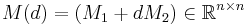 is the mass matrix,
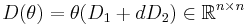 is the damping matrix,
 is the stiffness matrix,
 is the load vector,
  is the output matrix,
  is the state vector, and
  is the output response.
The variables and are the parameters of the system, where
is the width of the
bearing and is the rotation velocity along the -axis.
The interesting output  of the system is
  which is the
difference of the displacement
which is the
difference of the displacement  between the two red dots on
the same side of the bearing (see Fig.1). The number of degrees of freedom is
between the two red dots on
the same side of the bearing (see Fig.1). The number of degrees of freedom is  .
.
The interesting range for the parameters are: ![\theta\in [10^{-7}, 10^{-5}]](/morwiki/images/math/c/7/b/c7b0efa19e225aa5e038426cd80c3295.png) and
and ![d\in [1,2]](/morwiki/images/math/2/4/4/244c3333a4e36be25805ee4d952a245e.png) . The device works in the frequency range
. The device works in the frequency range ![f \in [0.025, 0.25]](/morwiki/images/math/8/f/1/8f1b9fd6143653e37abb4aeea17e1673.png) MHz.
MHz.
Data
The model is generated in ANSYS. The system matrices  , and
, and  are in the MatrixMarket format (http://math.nist.gov/MatrixMarket/), and can be downloaded here Gyroscope_modi.tgz. The matrix C defines the output, who has zeros at all the entries, except that on the 2315th entry, the value is -1, and on the 5806th entry, the value is 1. In MATLAB notation, it is
 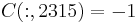 and
and 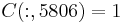 .
.
References
- ↑ J. Lienemann, D. Billger, E. B. Rudnyi, A. Greiner, J. G. Korvink, "MEMS Compact Modeling Meets Model Order Reduction: Examples of the Application of Arnoldi Methods to Microsystem Devices," Nanotech, 2004, pp. 303–306.
- ↑ 2.0 2.1 C. Moosmann, "ParaMOR Model Order Reduction for parameterized MEMS applications," PhD thesis, Department of Microsystems Engineering, University of Freiburg, Freiburg, Germany 2007.
[3] B. Salimbahrami, R. Eid, B. Lohmann, "Model Reduction by Second Order Krylov Subspaces: Extensions, Stability and Proportional Damping," IEEE International Symposium on Intelligent Control, 2006, pp. 2997–3002.
[4] L. Feng, P. Benner, J.G Korvink, "Subspace recycling accelerates the parametric macromodeling of MEMS" International Journal for Numerical Methods in Engineering, to appear.